After some discussions with the colleagues I was intrigued about how the DCF77 Signal is encoded and how hard it would be to practically decode this. So as any other I just started with the wikipedia page that offers a comprehensive information package about what is this signal and also how to decode the signal.
I also stumbled over a very interesting youtube video series about the Atmega324 wich got me intrigued on this quite cheap and also big (physically) uC from Atmel. I do personally recommend this video series for beginners.
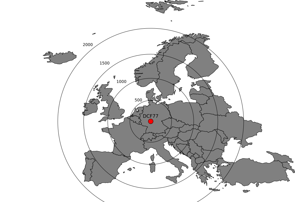
A quick background: the DCF77 is a longwave radio signal originating from Mainflingen (near Frankfurt). The signal encodes the Middle Europe Time. The signal reaches quite a long distance and can be very easily received from my location.
Hardware design
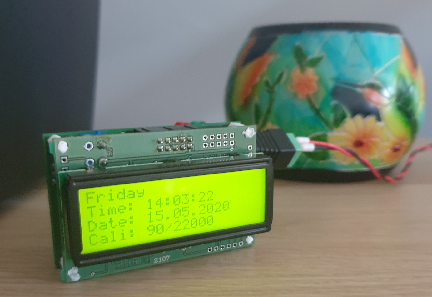
As I mentioned the primary goal is to build a simple watch. I decided to have a simple display because putting a motor with gears and stuff would be quite complicated. An old UART 20x4 display would do for now. The display also has a convenient size and connector where I was able to bind the 2 PCB in the end.
The uC controller used for the project is Atmega324 witch I bought from Reichelt (~2.80 €). I first started with a couple of samples where I tried to get all the code necessary for controlling my watch.
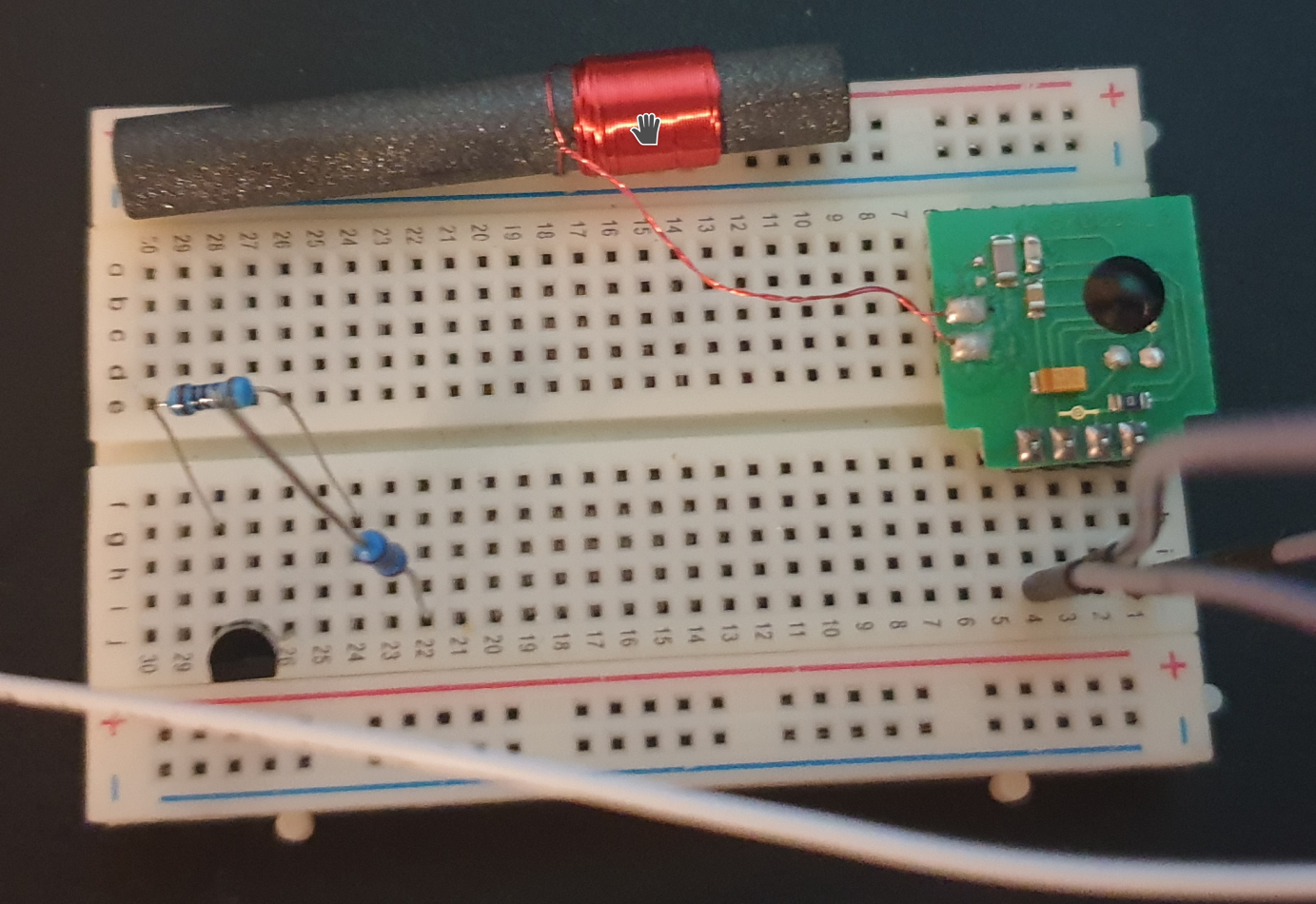
For receiving the signal and transforming-it into a digital one there are a few already made modules available.
Programming the Atmega324
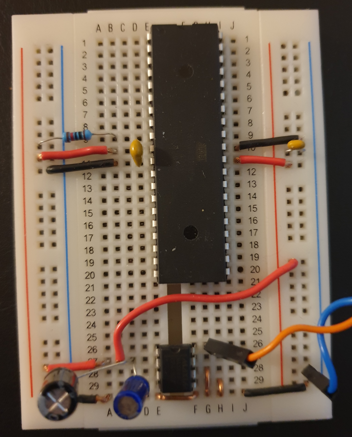
A small breadboard with a ICSP programmer is necessary for trying out the features of the uC. I did managed to program this also via JTAG but I think a little bit to much. To debug this one needs tha Atmel ICE that I do not have and don't need in the future.
For the SW I did use the Arduino provided package with the MightyCore board but tried to keep everything basic and not use too much from the convenience functions. I also really enjoi writting my code in vscode where there is a quite nice extension that allows the usage of the main ArduinoIDE commands.
In total I made about 10 programs building up all the modules that I would further need in the final clock firmware. I would like to give some more details on the steps and most important notes. One of the most important mention here is that the datasheet provides all the necessary information regarding the programming of the uC and a few example + diagrams.
01-atmega-blink
The basic hello wold for the uC.... here is just a matter of setting up the tools and the right connections. The uC just needs a few connections for this: the power pins (VCC, AVCC, GND) with a 100nF capacitor, the ICSP pins (MOSI, MISO, CLK, RESET, GND) and one green LED.
#include <avr/io.h>
#include "utils.h"

int main()
{
    // set PB0 as output
    DDRB |= _BV(DDB0);

    while (1) {
        PORTB |= _BV(PORTB0);
        delay_ms(1000);

        PORTB &= ~_BV(PORTB0);
        delay_ms(1000);
    }
}
This should do-it! There are a few settings to put into vscode in order to make the life easy... here is one that I found the most useful as it allowed me to use the intellisense and go to the symbol definition. This should go somewhere into the ".vscode/c_cpp_properties.json" file
"defines": [ "__AVR_ATmega324PA__" ],
02-atmega-interrupt
One of the most important features of a uC is it's interrupt capabilities. I do need this for measuring the time and also for triggering the user buttons actions in the end. On the Atmega this is realized by defining your interrupt handler using the ISR macro and enabling the interrupts with sei().
#include <avr/io.h>
#include <avr/interrupt.h>
#include "utils.h"

int main()
{
    DDRB |= (_BV(DDB2)|_BV(DDB0));
    PORTB &= ~(_BV(PORTB2)|_BV(PORTB0));

    // external interupt on rising edge
    EICRA |= (_BV(ISC21) | _BV(ISC20));
    EIMSK |= _BV(INT2);

    // enable interupts
    sei();

    while (1) {
        PORTB |= _BV(PORTB2);
        delay_ms(1000);

        PORTB &= ~_BV(PORTB2);
        delay_ms(1000);
    }
}

ISR(INT2_vect)
{
    if (bit_is_set(PINB, PINB0)) {
        PORTB &= ~_BV(PORTB0);
    } else {
        PORTB |= _BV(PORTB0);
    }
}
03-atmega-timer
The timers on the atmega are quite easy to work with. One needs to spend the most time on this topics when reading the datasheet. The timers are depending on the uC clock so it is always a good idea to keep this in mind when calculating things. Here is a simple example of a timer that is also coupled with an interrupt.
#include <avr/io.h>
#include <avr/interrupt.h>

int main()
{
    DDRB |= _BV(DDB0);
    PORTB &= ~_BV(PORTB0);

    TCCR1A = 0;
    TCCR1B = _BV(CS12) | _BV(CS10);   // 1024 prescaler (about 1ms@ 1MHz)

    // TOP value for the timer (when reached the interrupt will be triggered)
    TIMSK1 = _BV(OCIE1A);
    OCR1A = 1000 ;

    // enable interrupts
    sei();

    while (1) {
    }
}

ISR(TIMER1_COMPA_vect)
{
    if (bit_is_set(PINB, PINB0)) {
        PORTB &= ~_BV(PORTB0);
    } else {
        PORTB |= _BV(PORTB0);
    }

    // reset timer
    TCNT1H = 0;
    TCNT1L = 0;
}
04-atmega-gpio and 06-atmega-button
This is more or less one of the easiest thing to do on the uC. The only real challenge comes when the buttons needs debouching. Here I chose to use a timer to keep track of how long a button is pressed.
....

ISR(INT2_vect)
{
    // first time execution and the input is pulled low
    if ((status == 0) && !(PINB & _BV(PINB2))) {
        TCNT0  = 0;
        TCCR0B = _BV(CS02) | _BV(CS00); // 1024 prescaler (about 1ms@ 1MHz)
        status |= GPIO_BUTTON_PRESSED;
    }

    // the pin is pulled high so the button was released
    if ((status != 0) && (PINB & _BV(PINB2))) {
        status |= GPIO_BUTTON_RELEASED;
    }
}

ISR(TIMER0_COMPA_vect)
{
    TCNT0 = 0;

    // increment pressed duration
    if (bit_is_clear(PINB, PINB2)) {
        if (pressed_duration < 255) {
            pressed_duration++;
        }

        // after a minimum of 3 measurements set the debounced flag
        if (pressed_duration > 2) {
            status |= GPIO_BUTTON_PRESSED_DEBOUNCED;
        }
    }

    // increment released duration
    if (bit_is_set(PINB, PINB2)) {
        if (released_duration < 255) {
            released_duration++;
        }

        // after a minimum of 3 measurements set the debounced flag
        if (released_duration > 2) {
            status |= GPIO_BUTTON_RELEASED_DEBOUNCED;
        }
    }

    // stop the timer if the program resets the status
    if (status == 0) {
        TCCR0B = 0;
    }
}
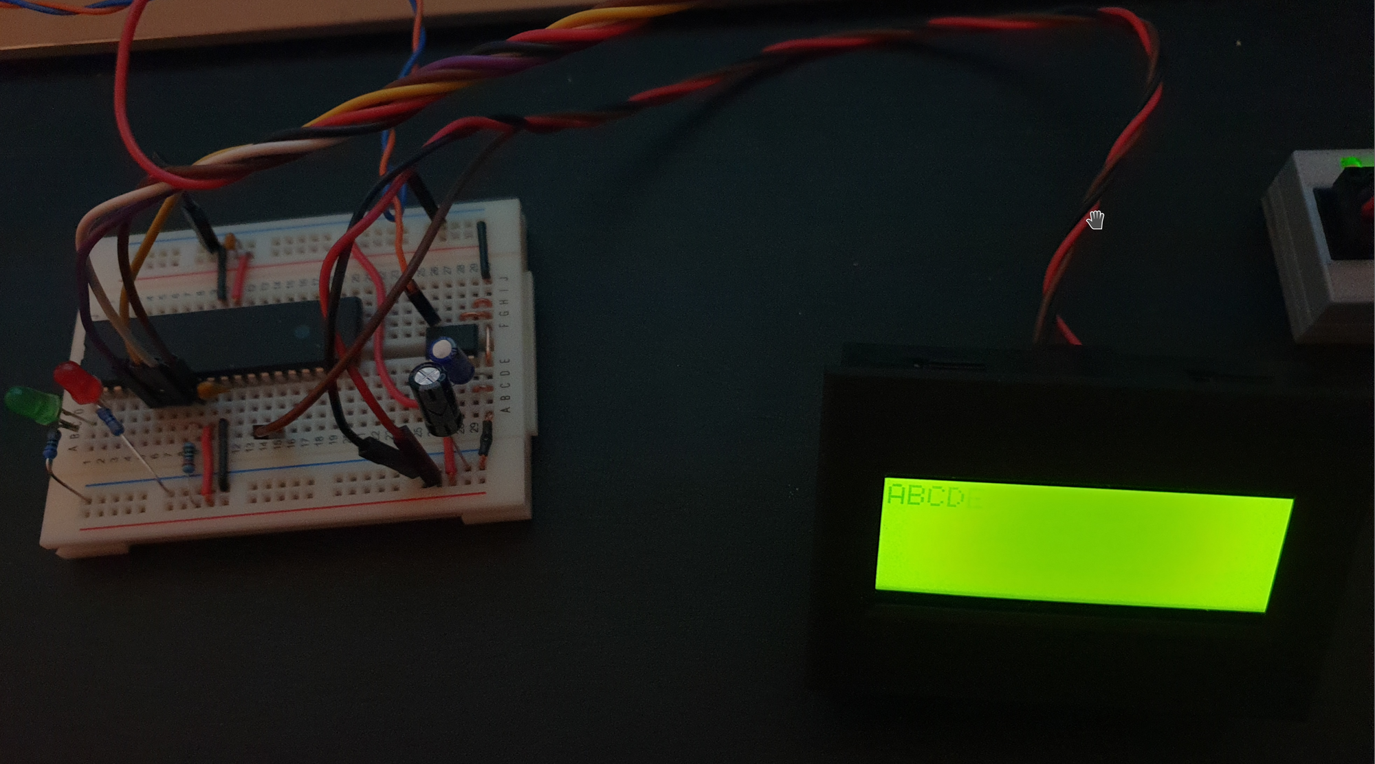
05-atmega-lcd
The LCD is a very simple UART controlled LCD. The datasheet would normally specify all commands and how to connect to the LCD. One things is that for my LCD type I needed to solder a couple of jumpers in order to get this working. The UART enable and transmit code can be directly copied from the Atmega datasheet
static void uart_init()
{
    /* Set baud rate */
    UBRR0H = 0;
    UBRR0L = 12;

    UCSR0A = _BV(U2X0);
    /* Enable the transmitter */
    UCSR0B = _BV(TXEN0);

    /* Set frame format: 8data, 1stop bit */
    UCSR0C = _BV(UCSZ01) | _BV(UCSZ00);
}

static void uart_transmit(char data)
{
    /* Wait for empty transmit buffer */
    while (!(UCSR0A & _BV(UDRE0)))
        ;
    /* Put data into buffer, sends the data */
    UDR0 = data;
}
07-atmega-eeprom
The same thing as with the UART there is an example provided. On thing is that once the uC is re-flashed the content of the eeprom is lost.
static unsigned char read(unsigned int address)
{
    /* wait for completion of previous write */
    loop_until_bit_is_clear(EECR, EEPE);

    /* set up address register */
    EEAR = address;

    /* start eeprom read by writing EERE */
    EECR |= _BV(EERE);

    return EEDR;
}

static void write(unsigned int address, const unsigned char data)
{
    /* wait for completion of previous write */
    loop_until_bit_is_clear(EECR, EEPE);

    /* set up address and Data Registers */
    EEAR = address;
    EEDR = data;

    /* write logical one to EEMPE */
    EECR |= _BV(EEMPE);
    /* start eeprom write by setting EEPE */
    EECR |= _BV(EEPE);
}
08-atmega-input-capture
This is a special timer mode that is required for the DCF77 pulse measurement. It is a convenient feature of the timer that I decide to use from within an interrupt. The interrupt edge needs to be toggled every time in order to measure both the low and high duration.
ISR(TIMER1_CAPT_vect)
{
    if (bit_is_clear(TCCR1B, ICES1)) {
        duration_high = ICR1;
        PORTB |= _BV(PORTB0);
    } else {
        duration_low = ICR1;
        PORTB &= ~_BV(PORTB0);
    }
    TCCR1B ^= _BV(ICES1);
    TCNT1 = 0;
}
09-atmega-dcf77
This is the sample program for the evaluation of the DCF77 module and where I implemented the protocol decoding. As i wanted to store everything related to the 1 minute cycle of the DCF77 i have used a 64 bit int. Here one needs to be careful when doing bit operation (always cast to the right type!).
// decode one bit from the data buffer
#define DCF77_DECODE_DATA(bit, value)  ((data & ((unsigned long long)1 << bit)) ? value : 0)
10-atmega-clock-firmware
And finally.... the clock firmware! All this can be found on github: https://github.com/bdmihai/atmega
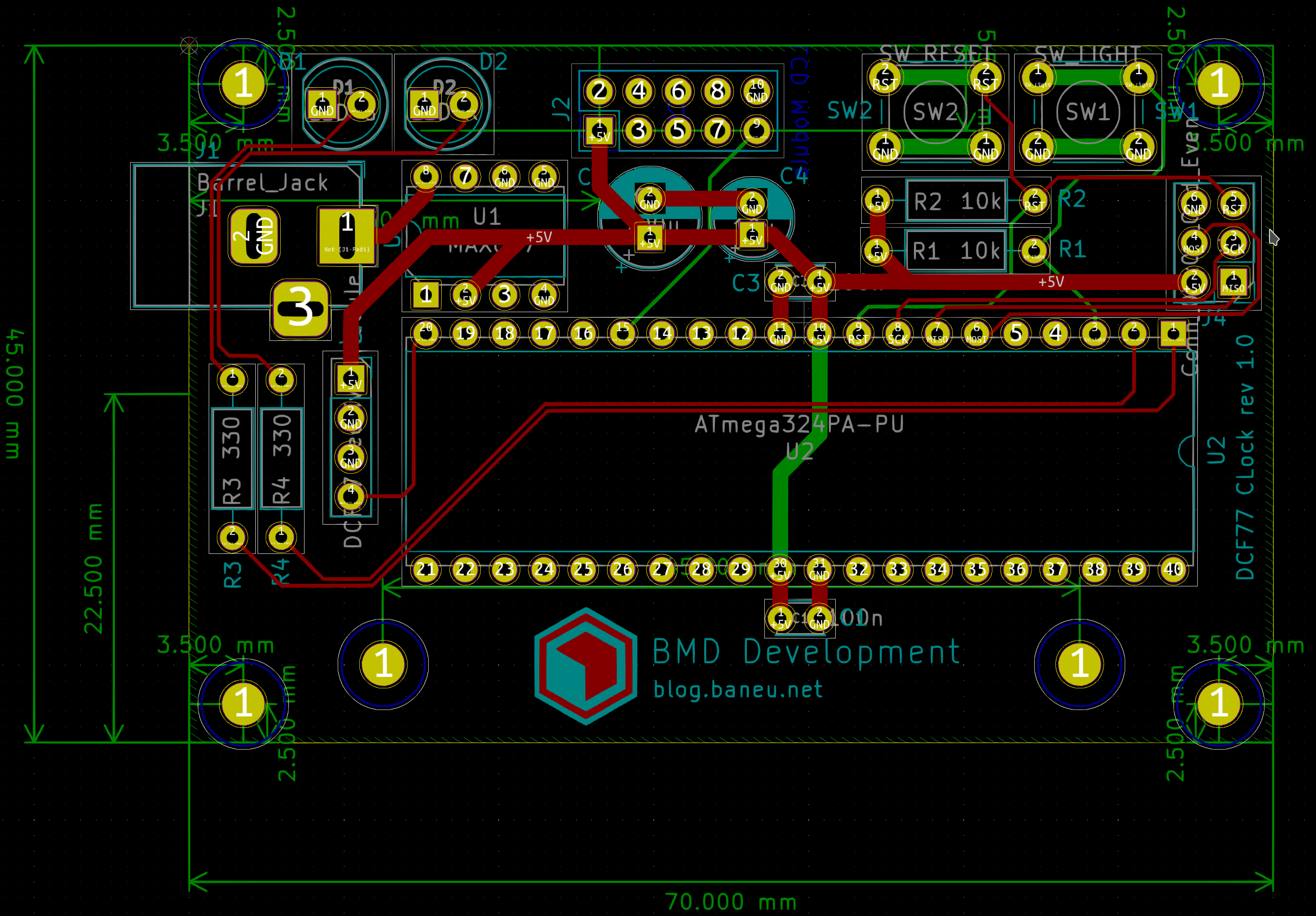
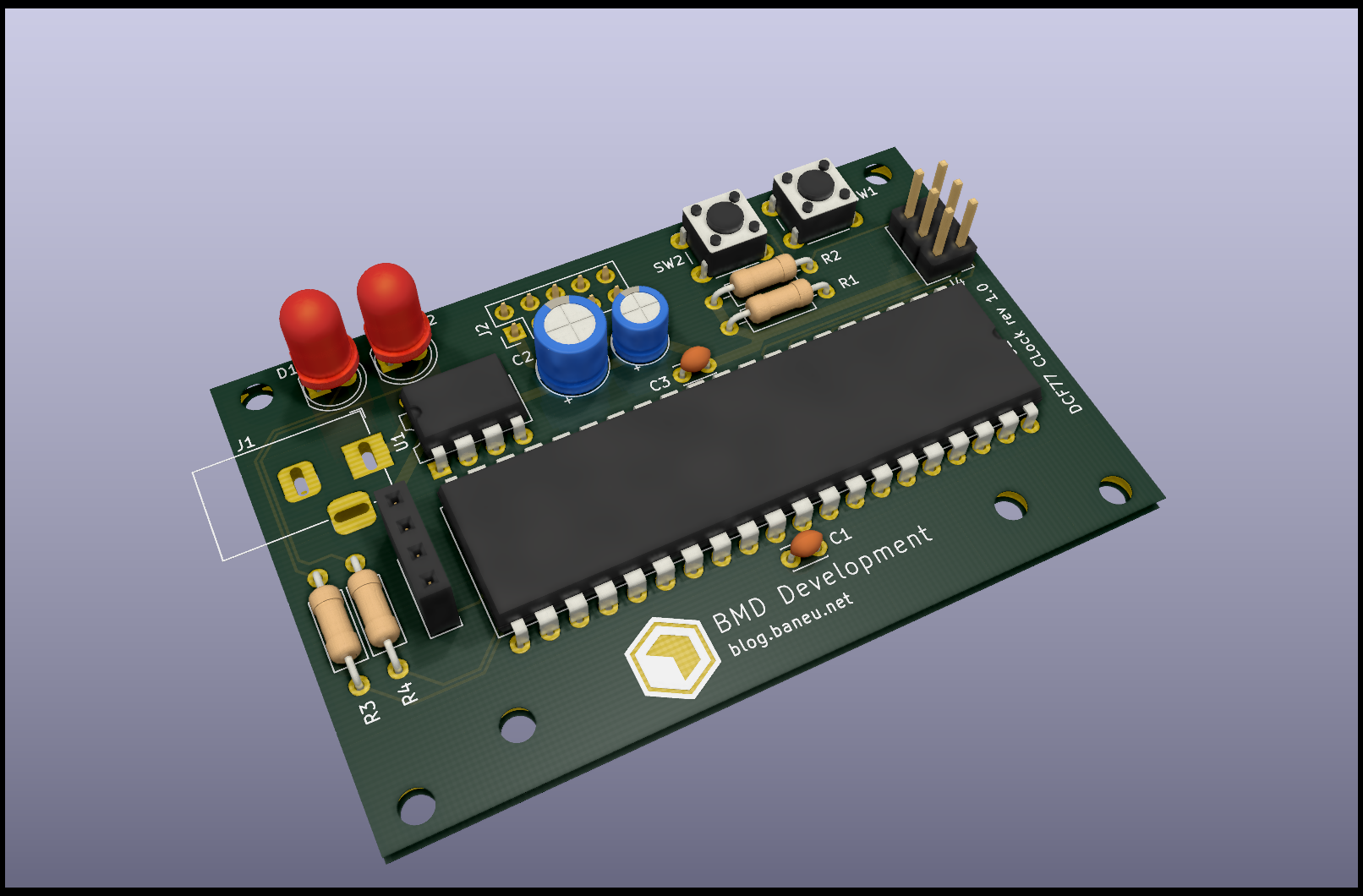
PCB design
I made my PCB design using Kicad. The circuit diagram I already had from the design phase so the only part was the layout. I did measured my LCD board and tried to get exactly the same size and also the critical placement of the mounting holes and the inter PCB connector.
I ordered my PCB from aisler. The quality of their boards is good and this one was quite small and cheap.
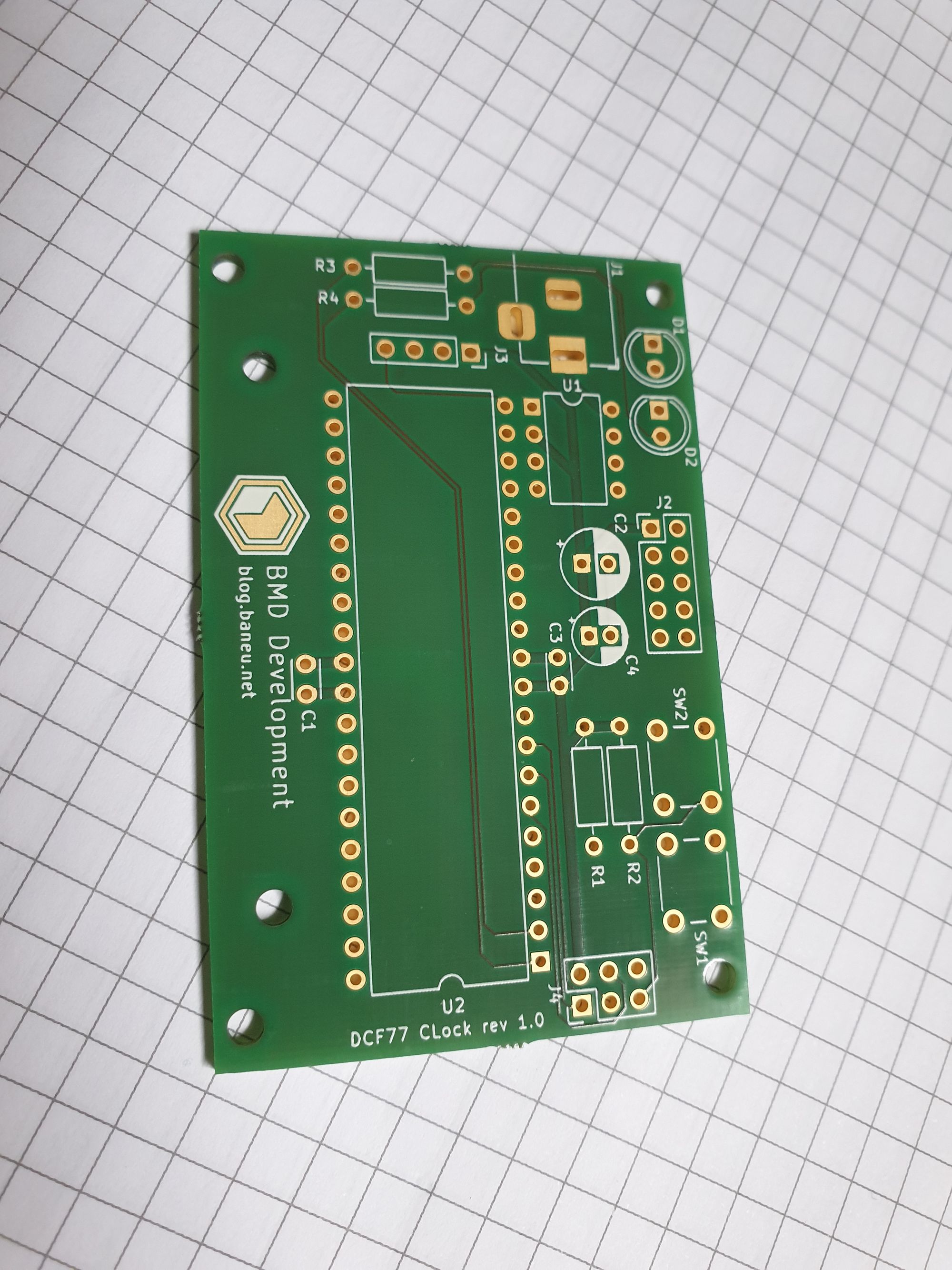
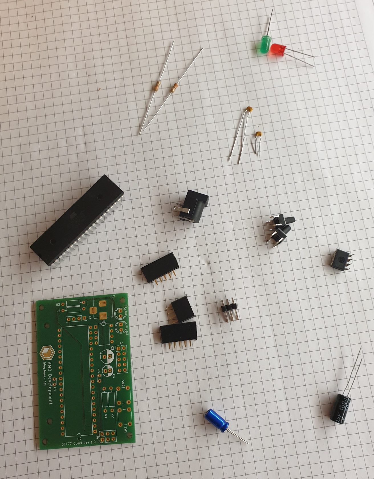
Build
Once the PCB's have arrived I gathered all components and hand soldered them. Everithing was through hole so it went very easy and without any problems.
After soldering all components I did managed to find a small issue :( - the RX pin was used instead of the TX. A quick fix and everything works perfect.
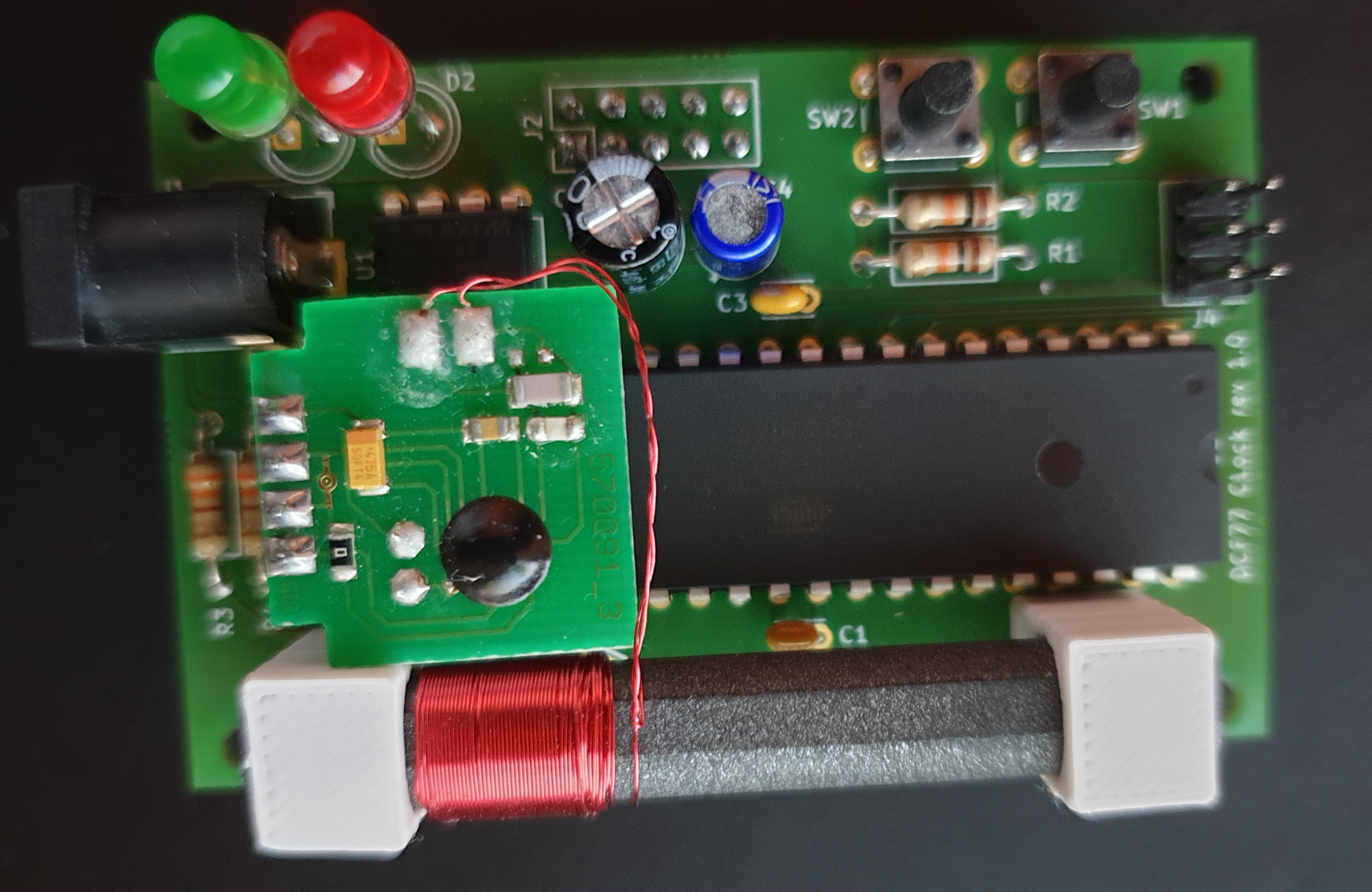
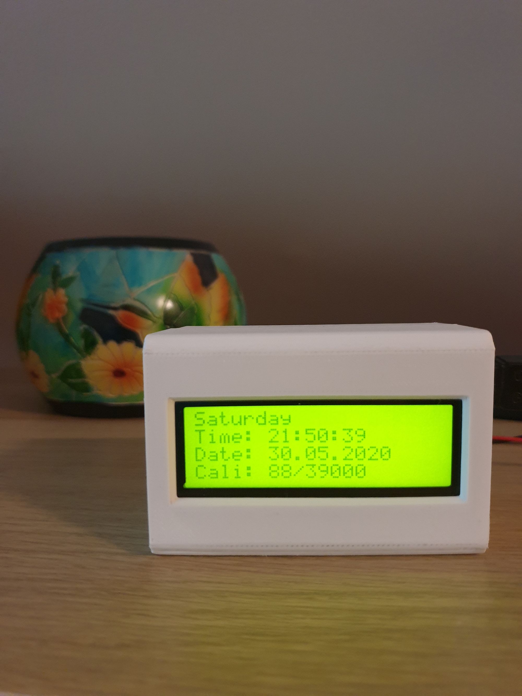
Overall I think is a nice 2 weekends projects and I did had some fun building-it. It still needs a couple of things be improved: power consumption and 3d printed enclosure :)