Since the Cortex M4 offers some clear advantages and improvements over the M3 I started working on this as a side project. The goal is to make this a feasible platform for highly optimized, low level C code projects and use the uC for standard communication as infrastructure microcontroller.
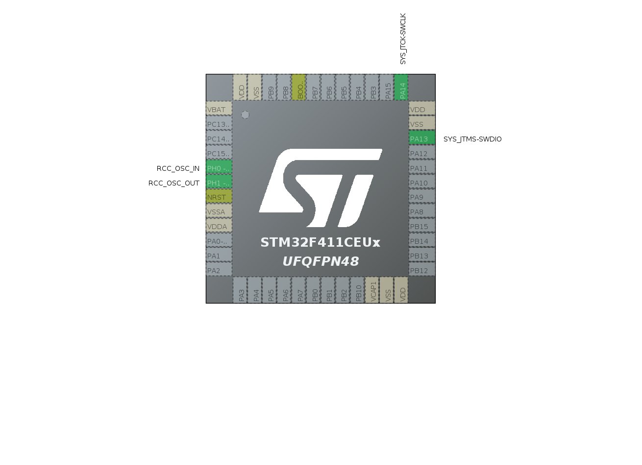
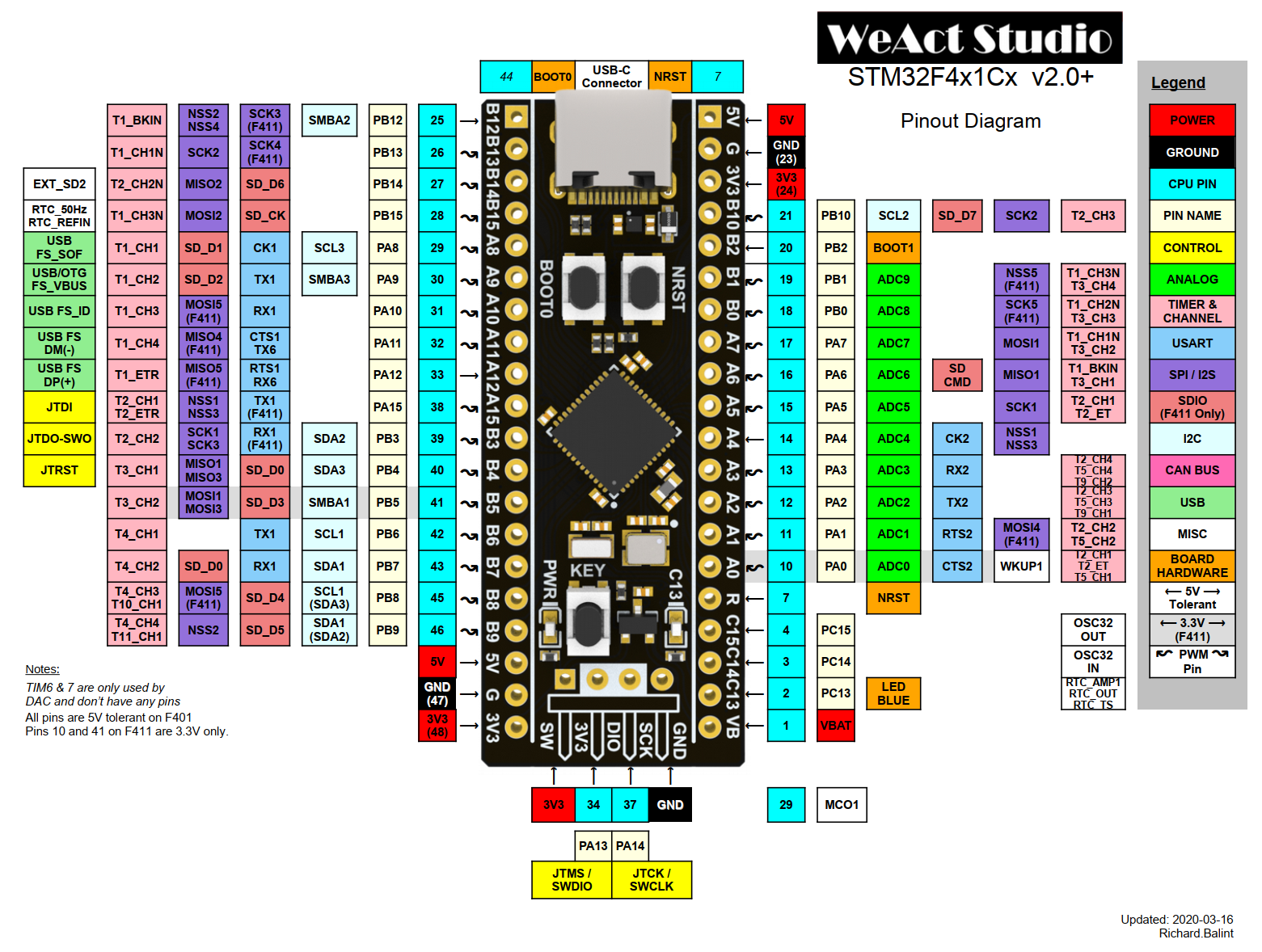
The uC that I have chosen is the STM32F411CE included in the MiniF4-STM32F4x1 development board. This is a very simple and cheap board the necessary HW for the development setup. Main features of the uC are: ARM Cortex M4 with FPU running up to 100 MHz freq, 512 KB Flash, 128 KB Ram. Peripherals are the usual stuff: I2C, SPI, USB.
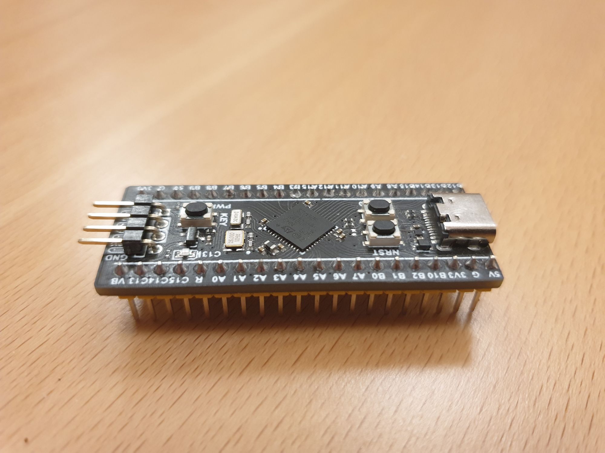
Development Board
As mentioned before, I have bought my Mini's F4 from a reputable Chinese store and receive them quite fast. The quality and overall design of the boards is quite good and I can only recommend them.
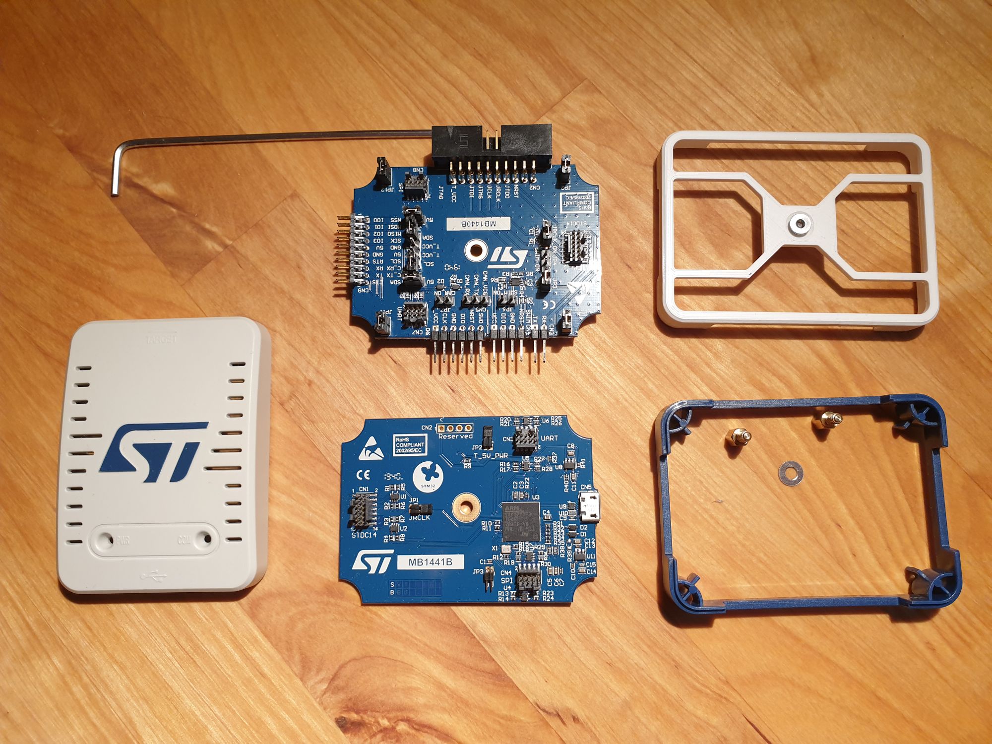
I will power the board separately and use a ST-Link V3 to flash the sw and debug the programs. There are cheaper options than the V3 but I do like the board extension that includes a Bridge feature and 2 virtual COM ports. I think is also reasonably fast @24000 KHz but this needs to be configured in the OpenOCD config files. Speaking of OpenOCD this is one of the mandatory tools that needs to be installed (locally compiled in my case) and eventually updated to fit the target board/debugger. This can be cloned from the official OpenOCD repository clone and compiled. The configuration files can be then locally altered to take advantage of the V3 higher speed.
# Boost JTAG frequency
adapter speed 24000
Build environment (Qbs)
There are quite a few options available (including STM32CubeIDE) that offers a good starting point. I did want to use the Qbs build system as I found-it to be very intuitive and powerful. Taking into account that I want to have full control over the compilation process I build up my own stm32.qbs module instead of using the already existing cpp one. The modules in Qbs can be inherited so I wanted to use this strategy for my setup. There is a base stm32 module that get inherited by the stm32f4 and finally by the actual uC specific module stm32f411ce. At each level properties defined in the stm32 base are overwritten with specific values like compiler flags and memory specifications. The tools (compiler, linker, etc) will use the information from all 3 levels in the compilation process.
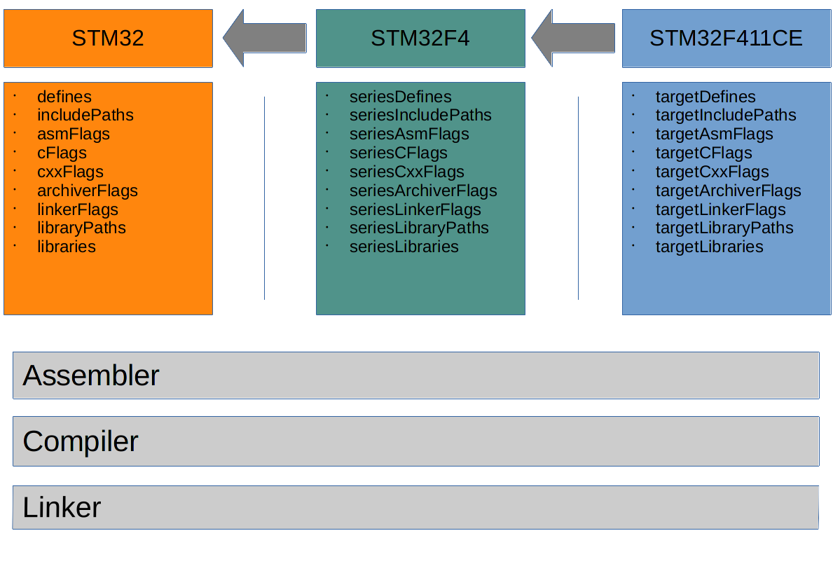
Only one module can be instantiated and this is selected by the qbs.targetPlatform that is specified in the command line call.
CONFIG_MCU = STM32F411CE
...

build:
	/usr/bin/qbs build -d build -f source/project.qbs --jobs 16 config:$(CONFIG_MCU) qbs.installRoot:bin qbs.targetPlatform:$(CONFIG_MCU)
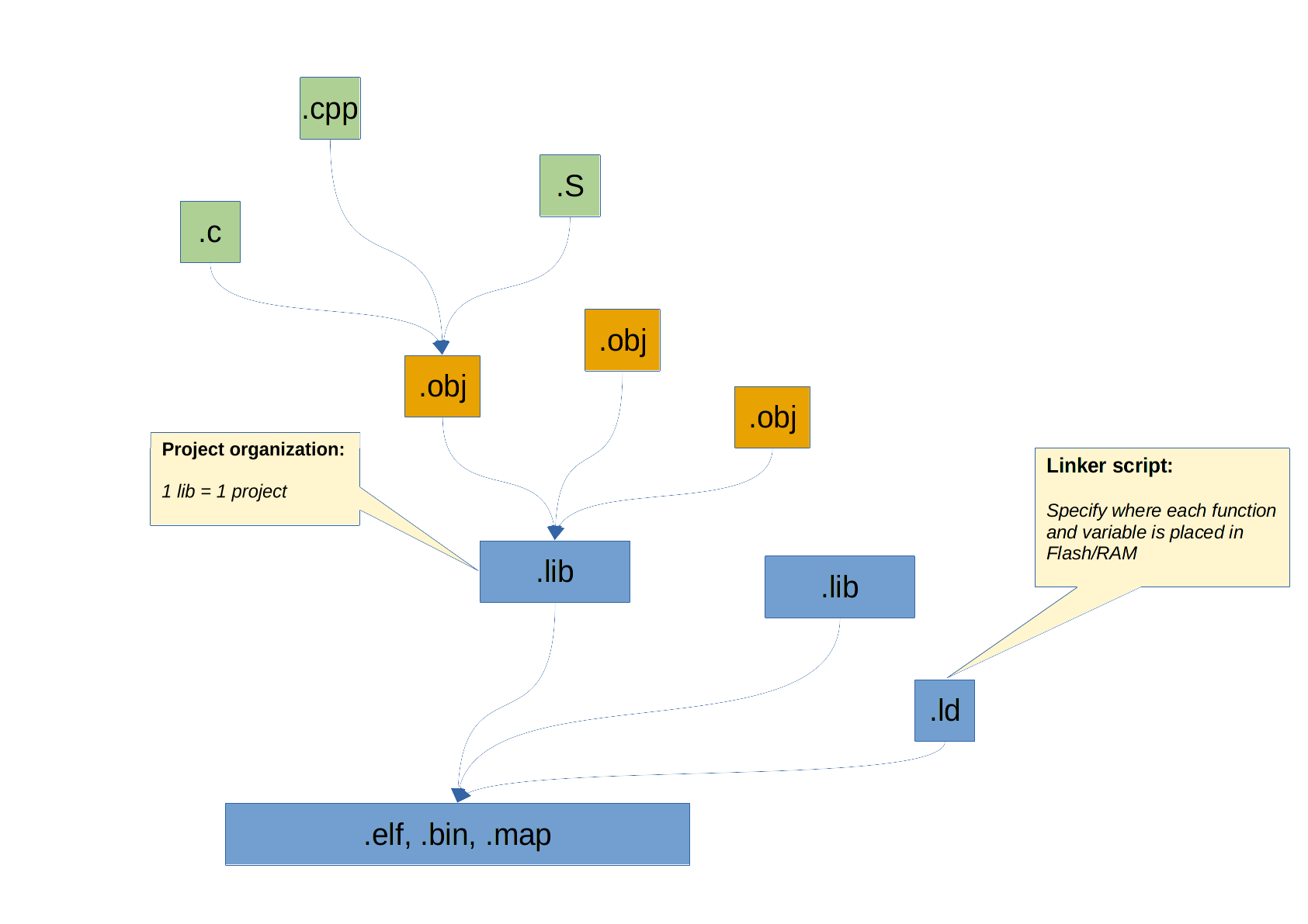
I included a project separation concept into the build process that allows the split-up of projects into smaller components. This is similar to the Arduino build where each library gets compiled into a lib and at the end everything is linked together. For this Qbs provides the Product and Project build-in items.
Setting up this kind of build environment offers a lot of control and insight on the uC and the tool chain used. A lot of information comes from understanding and experimenting with different compiler flags and options. I have analysed and reused two build systems before getting to this stage that I would like to mention here: the make based build system of esp-idf and the stm32-base.
Documentation
The most important document required for starting with any stm32 uC is the Reference Manual. Here every feature and peripheral is explained and the registers are described. Secondly the datasheet is necessary as some information and electrical characteristics are detailed here. The STM32CubeIDE will provide tease and also a very intuitive GUI to setup the pin assignment and clocks. This will use the HAL but one can dig a little deeper and find out exactly what registers are changed (the target is to handle the low level myself).
Interacting with the target
OpenOCD provides the necessary commands to interact with the target microcontroller. It provides basic commands like reset and flash but also allows to connect with gdb for debugging.
The most simple command is the reset command. The commands can be issued using the -c command line argument
openocd -s $(CONFIG_OPENOCDCONFIGDIR) -f $(CONFIG_OPENOCD_INTERFACE) -f $(CONFIG_OPENOCD_BOARD) -c "init; reset; exit"
or via telnet on the port 4444
telnet 127.0.0.1 4444
> reset
More details can be found online in the OpenOCD documentation:
A Makefile is available hier to execute the necessary tools with the right parameters.
Source code
The source code for this article can be found in github: stm32f411ce-blink. The project is splitt-up so that the common source code is located into independent submodules that can be separately updated and shared (the qbs module, freertos, linker, etc).
Linker
The linker file is what defines the memory layout of the program, where every function shall be places, where the variables should reside. For each uC there is a little bit of difference as each one has different amount of flash and ram, this is why there is a common.ld and a specific uC .ld script. Only the specific one is included into the .qbs project for compilation.
MEMORY {
    FLASH   (rx) : ORIGIN = 0x08000000, LENGTH = 512K
    RAM    (rwx) : ORIGIN = 0x20000000, LENGTH = 128K

    CCMRAM (rwx) : ORIGIN = 0x10000000, LENGTH = 0K
}

INCLUDE common.ld
The example above shows how the memory is defined. Further the Flash is split into sections that have a dedicated purpose and needs to be placed at various addresses. The first thing in needs to be the ISR vector that is located at the first address in flash, then code and constants.
Ram is constituted from variables (initialized and uninitialized), heap and stack. The heap section is somehow artificial and used by the FreeRTOS for dynamic memory allocation. The .data section will have a flash section equal with the allocated ram amount. The actual copying of the values in ram happens in the startup phase.
https://github.com/bdmihai/stm32-linker
Startup
This small part defines the first steps executed by the controller and it defines the isr vector. This, like the linker, is build to be portable to more uC types and it also has a common and a specific part. Is written in assembly but is quite straight forward.
https://github.com/bdmihai/stm32-startup
Cmsis and HAL
Tease are the two libraries that come normally with the STM32CubeIDE and are directly provided by ST. They contain all necessary definitions and also the hardware abstraction layer if this is required by the application.
https://github.com/bdmihai/stm32-cmsis
https://github.com/bdmihai/stm32-hal
FreeRTOS
Is a must in all modern application to have a underlying OS that manages your task. It basically allows to take full advantage of the processing power of the microcontroller and do a lot of things in parallel.
https://github.com/bdmihai/stm32-freertos
App
Hier the user code starting with the main function is written. The very simple blink sketch is the uC "Hello World" program so this is why I have this as my first example.