When communication with other devices (usually slower ones) the DMA offers the advantage of relieving the microcontroller from the cumbersome task of controlling the peripherals, copying bytes or waiting for communication events. Here I have a classical example where I want to use the DMA to read the data from a external eeprom.
Peripheral settings and clock
To enable the I2C interface the APB1 clock needs to be set up and then enabled. The same for the DMA with the exception that the DMA is connected to the AHB.
    /* enable AHB1 ports clock */
    ...
    SET_BIT(RCC->AHB1ENR, RCC_AHB1ENR_DMA1EN);

    /* enable APB1 devices */
    SET_BIT(RCC->APB1ENR, RCC_APB1ENR_I2C1EN);
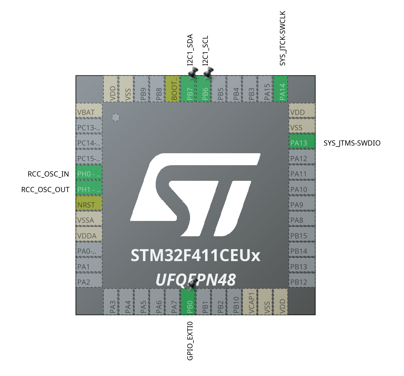
The pins 6 and 7 of the port B can be used as I2C pins. First they need to be configured as alternate function according to the datasheet (full table with the alternate functions for all the pins). The configuration is high speed, open drain with no pull up or down resistor.
    /* configuration of the I2C GPIO pins */
    MODIFY_REG(GPIOB->MODER, GPIO_MODER_MODER6_Msk, GPIO_MODER_MODER6_1);                                   /* set the pin as alternate function */
    MODIFY_REG(GPIOB->MODER, GPIO_MODER_MODER7_Msk, GPIO_MODER_MODER7_1);                                   /* set the pin as alternate function */

    MODIFY_REG(GPIOB->AFR[0], GPIO_AFRL_AFSEL6_Msk, GPIO_AFRL_AFSEL6_2);                                    /* AF4 - I2C1_SCL */
    MODIFY_REG(GPIOB->AFR[0], GPIO_AFRL_AFSEL7_Msk, GPIO_AFRL_AFSEL7_2);                                    /* AF4 - I2C1_SDA */

    MODIFY_REG(GPIOB->OTYPER, GPIO_OTYPER_OT6_Msk, GPIO_OTYPER_OT6);                                        /* open drain */
    MODIFY_REG(GPIOB->OTYPER, GPIO_OTYPER_OT7_Msk, GPIO_OTYPER_OT7);                                        /* open drain */

    MODIFY_REG(GPIOB->OSPEEDR, GPIO_OSPEEDR_OSPEED6_Msk, GPIO_OSPEEDR_OSPEED6_0 | GPIO_OSPEEDR_OSPEED6_1);  /* high speed */
    MODIFY_REG(GPIOB->OSPEEDR, GPIO_OSPEEDR_OSPEED7_Msk, GPIO_OSPEEDR_OSPEED7_0 | GPIO_OSPEEDR_OSPEED7_1);  /* high speed */

    MODIFY_REG(GPIOB->PUPDR, GPIO_PUPDR_PUPD6_Msk, 0);                                                      /* no pull up, no pull down */
    MODIFY_REG(GPIOB->PUPDR, GPIO_PUPDR_PUPD7_Msk, 0);                                                      /* no pull up, no pull down */
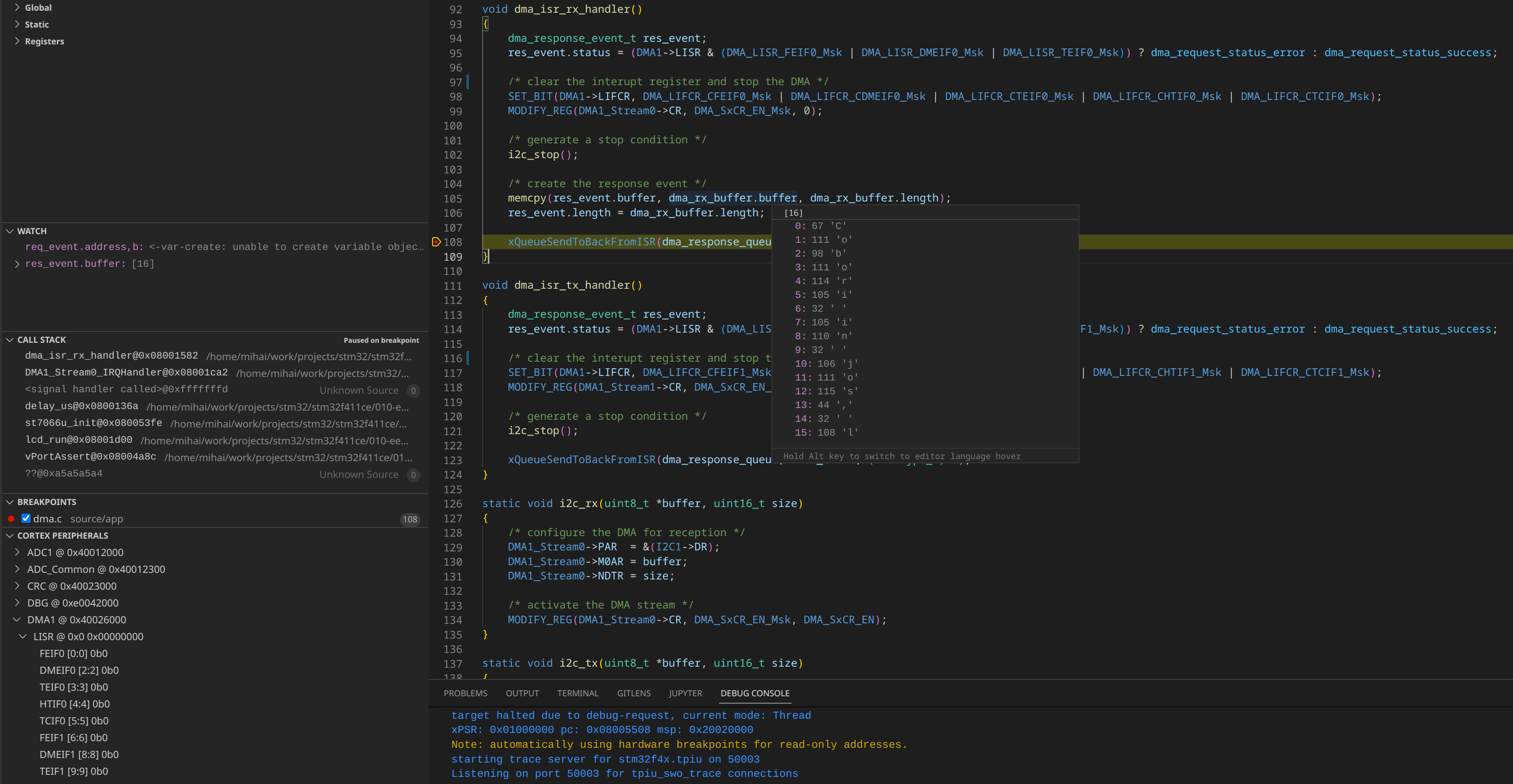
The DMA requires 2 interrupts to be active. I will use the interrupts in order to trigger the next steps in the update process.
    /* enable interupt */
    ...
    NVIC_SetPriority(DMA1_Stream0_IRQn, NVIC_EncodePriority(NVIC_GetPriorityGrouping(), 11 /* PreemptPriority */, 0 /* SubPriority */));
    NVIC_SetPriority(DMA1_Stream1_IRQn, NVIC_EncodePriority(NVIC_GetPriorityGrouping(), 11 /* PreemptPriority */, 0 /* SubPriority */));

    ...
    NVIC_EnableIRQ(DMA1_Stream0_IRQn);
    NVIC_EnableIRQ(DMA1_Stream1_IRQn);

void DMA1_Stream0_IRQHandler(void)
{
  dma_isr_rx_handler();
}

void DMA1_Stream1_IRQHandler(void)
{
  dma_isr_tx_handler();
}
The I2C clock initialization needs to consider the target device requirements, in my case the eeprom. The following formula is used: thigh+tlow = 3 * CCR * tpclk => CCR = pclk / (3*400kHz). One additional setting is to enable the last NACK automatic send in DMA mode.
The DMA setup is relatively simple following the documentation. One important thing to consider is that the streams must be disabled before performing any configuration. In my case DMA1 (Stream0 and Stream1) are connected to the I2C peripheral but here are usually multiple options.
Tasks and dataflow
The backbone of the application is the FreeRTOS operating system. This is basically handling in parallel the 4 tasks: encoder, dma, lcd and the user handler.
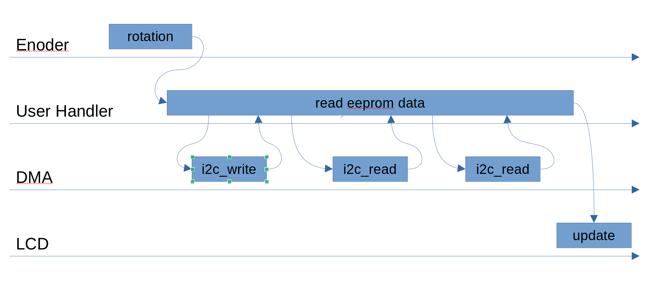
Communication is ensured via queues and all events are triggered by the rotary encoder rotation.
Programming and debugging