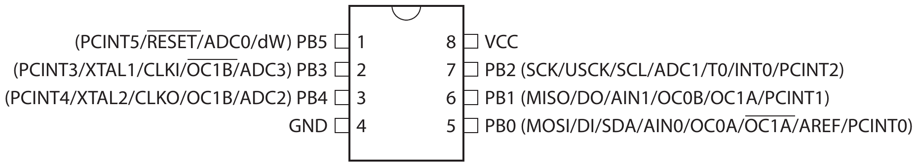
ATtiny85 is a small form factor microcontroller from Microchip (originally developed by ATMEL). It has 8k of flash and 512 bytes of RAM, 6 I/O pins with various functionality. Due to its small form factor is ideal for small projects and learning.
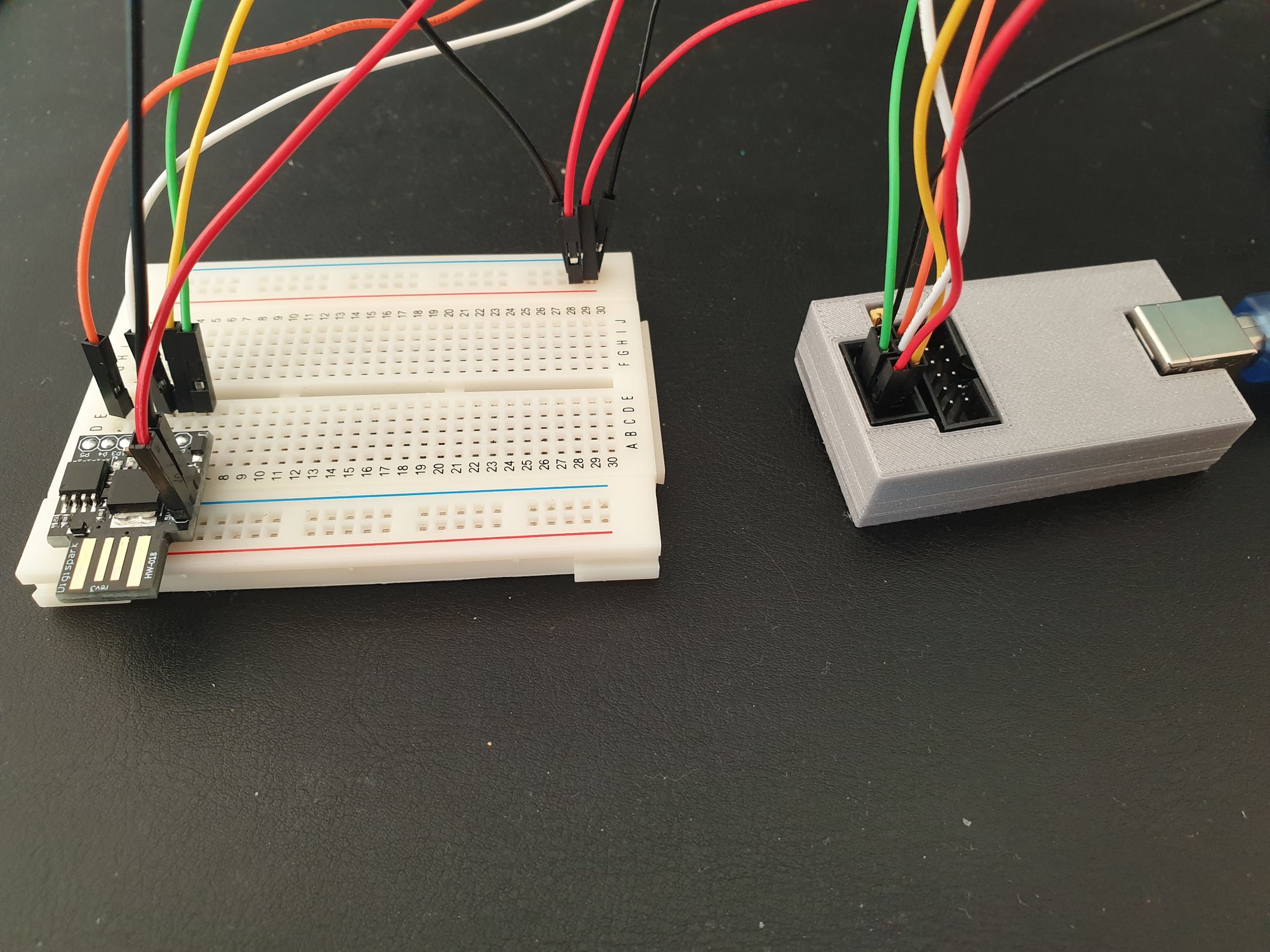
The advantage is that it is quite simple and due to this it makes for a good starting point if someone starts learning programming of microcontrollers. As starting point the my recommendation is to get the Digispark USB Development Board as it allows to program the uC directly via USB without the need of extra HW. It is inexpensive and SW for development is already available.

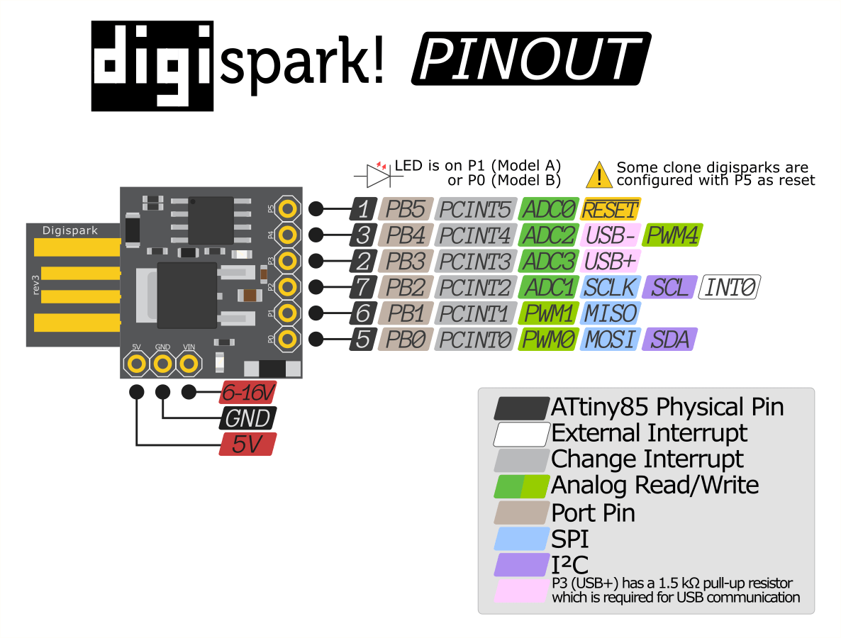
For development the Arduino board can be installed in the Arduino IDE. A tutorial is available here: http://digistump.com/wiki/digispark/tutorials/connecting
Datasheet for the ATtiny can be downloaded from the Microchip site.
A little care needs to be taken when connecting directly to the PC USB port since it does not have proper protection and can damage the USB port.
First program - Blink
The first thing to do is to flash the first program on the tiny. This is achieved using the already programmed bootloader. To program the device unplug-it from the USB, start the command line flashing utility (usually performed by the Arduino IDE), and then plug in the digispark into the USB.
#define __AVR_ATtiny85__

#include <avr/io.h>
#include <util/delay.h>

void setup()
{
  DDRB |= _BV(DDB1); // set PB1 as output
}

void loop()
{
  PORTB |= _BV(PB1);
  _delay_ms(1000);
  PORTB &= ~_BV(PB1);
  _delay_ms(1000);
}
A simple LED controller
After the very simple example is time to test the input of the tiny. This is achieved by checking the PORTB for the bit corresponding to the input pin. As a quick debouching the sleep mechanism is used. Here is the pin change interrupt is used to wake the microcontroller.
#define __AVR_ATtiny85__

#include <avr/io.h>
#include <avr/sleep.h>

void setup()
{
  DDRB |= _BV(DDB1);
  DDRB &= ~_BV(DDB2);
  PORTB &= ~_BV(PB1);
}

void loop()
{
  if (bit_is_set(PINB, PINB2)) {
    PORTB |= _BV(PB1);
  }
  else {
    PORTB &= ~_BV(PB1);
  }

  system_sleep();
}

void system_sleep()
{
    cli();                                  // Disable interrupts
    GIMSK |= _BV(PCIE);                     // Enable Pin Change Interrupts
    PCMSK |= _BV(PCINT2);                   // Turn ON interrupt pins
    sei();                                  // Enable interrupts

    ADCSRA &= ~_BV(ADEN);                   // ADC off
    set_sleep_mode(SLEEP_MODE_PWR_DOWN);
    sleep_enable();                         // Sets the Sleep Enable bit in the MCUCR Register (SE BIT)
    sleep_cpu();                            // sleep
    sleep_disable();                        // Clear SE bit
    ADCSRA |= _BV(ADEN);                    // ADC on

    cli();                                  // Disable interrupts
    PCMSK &= ~_BV(PCINT2);                  // Turn OFF interrupt pins
    sei();                                  // Enable interrupts
}

ISR(PCINT0_vect)
{
}
PWM Control
There are a maximum of 3 PWM pins on the attiny (some tricks are needed to get 4...but it is possible). 2 of them are very easy to use and conveniently placed on PB0 and PB1. Here is a very basic example:
#define __AVR_ATtiny85__
#define F_CPU 16500000
#include <avr/io.h>
#include <avr/sleep.h>
#include <util/delay.h>
void setup()
{
// set the pin as output
DDRB = _BV(DDB1);
// set the fast PWM output on OC0B, Inverting Mode
TCCR0A = (3 << COM0B0) | (3 << WGM00);
// clkI/O/64 prescaler and Fast PWM to 0xFF from BOTTOM
TCCR0B = (3 << CS00);
// comparator value
OCR0B = 255;
}
void loop()
{
for (uint8_t i=255; i>0; i--) {
OCR0B = i;
_delay_ms(10);
}
for (uint8_t i=0; i<255; i++) {
OCR0B = i;
_delay_ms(10);
}
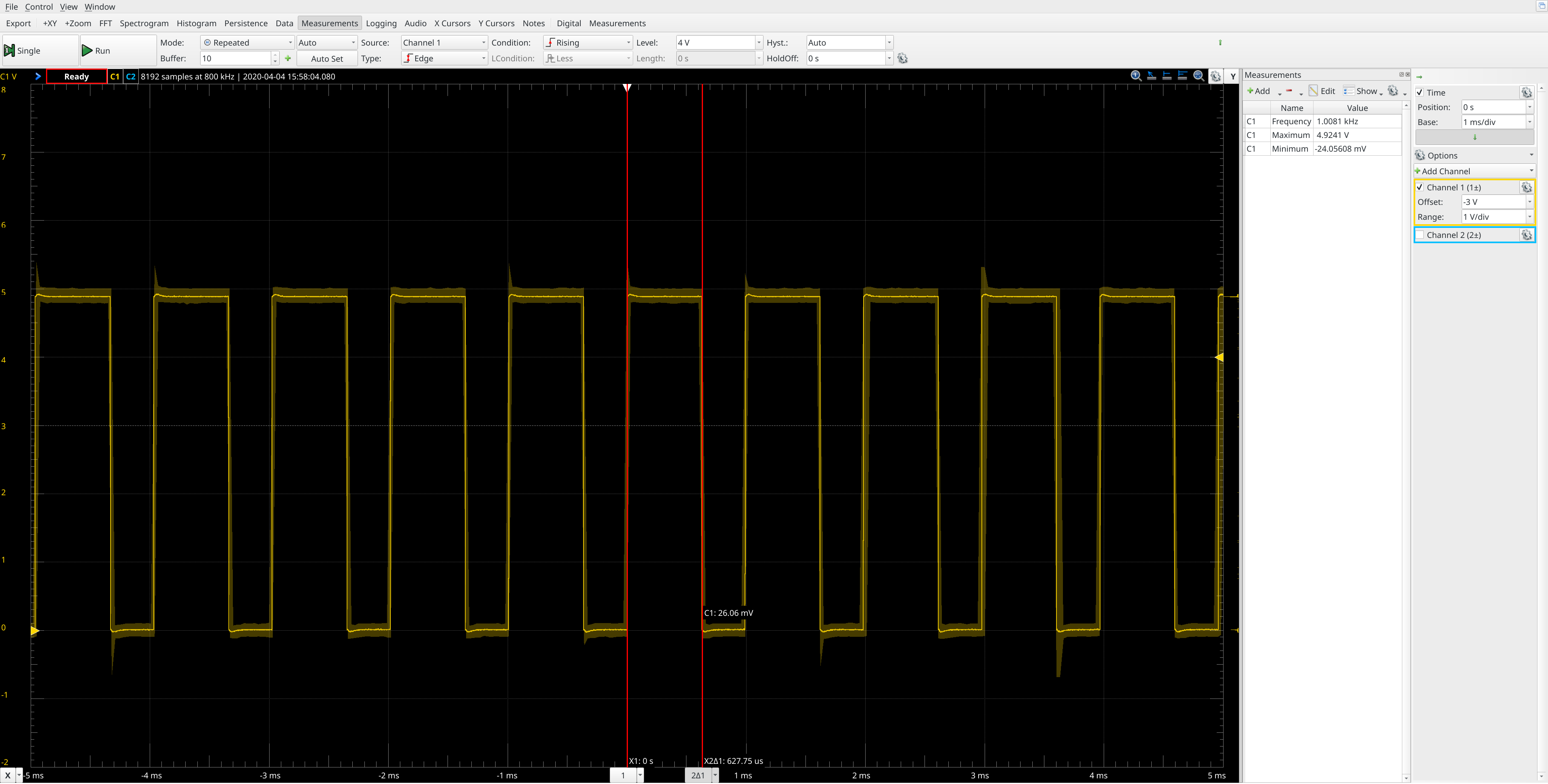
}
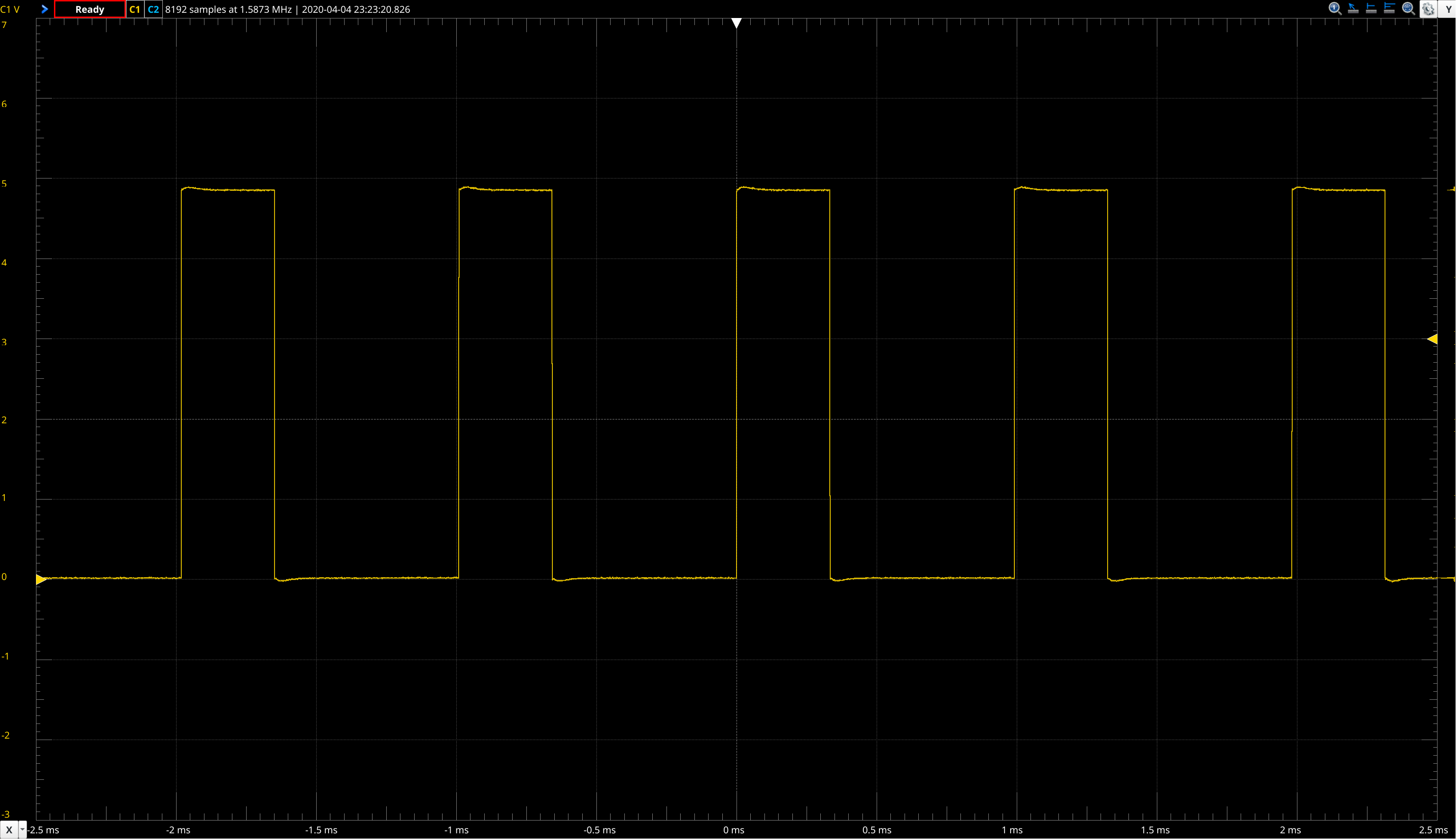
The output on pin 1 looks like this:
Inputs - rotary encoder
The ATtiny inputs can be mapped to interrupts and monitored. Here, a classic example is the monitoring of the rotary encoder using interrupts. The rotary encoder has pull-up resistors on both outputs.
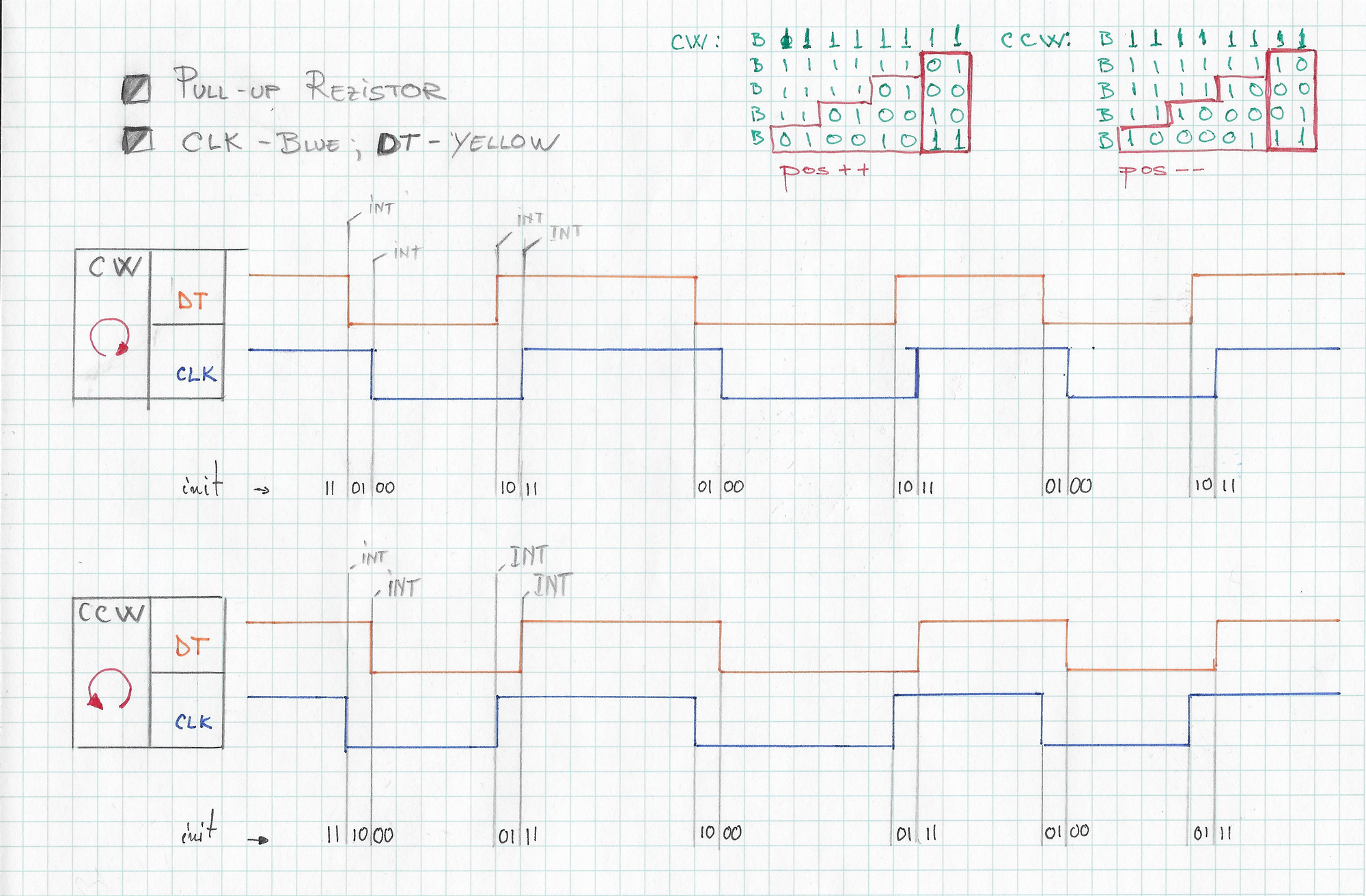
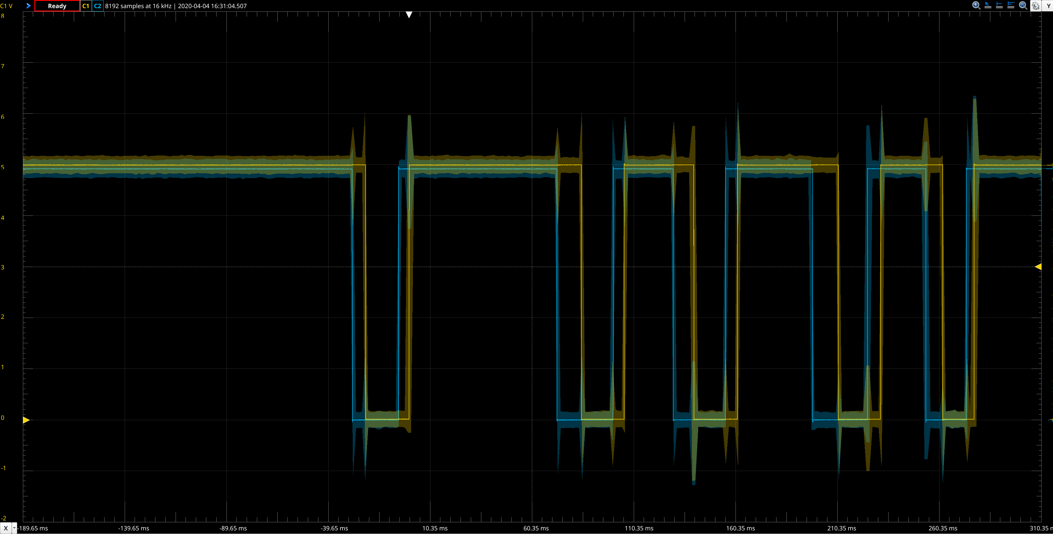
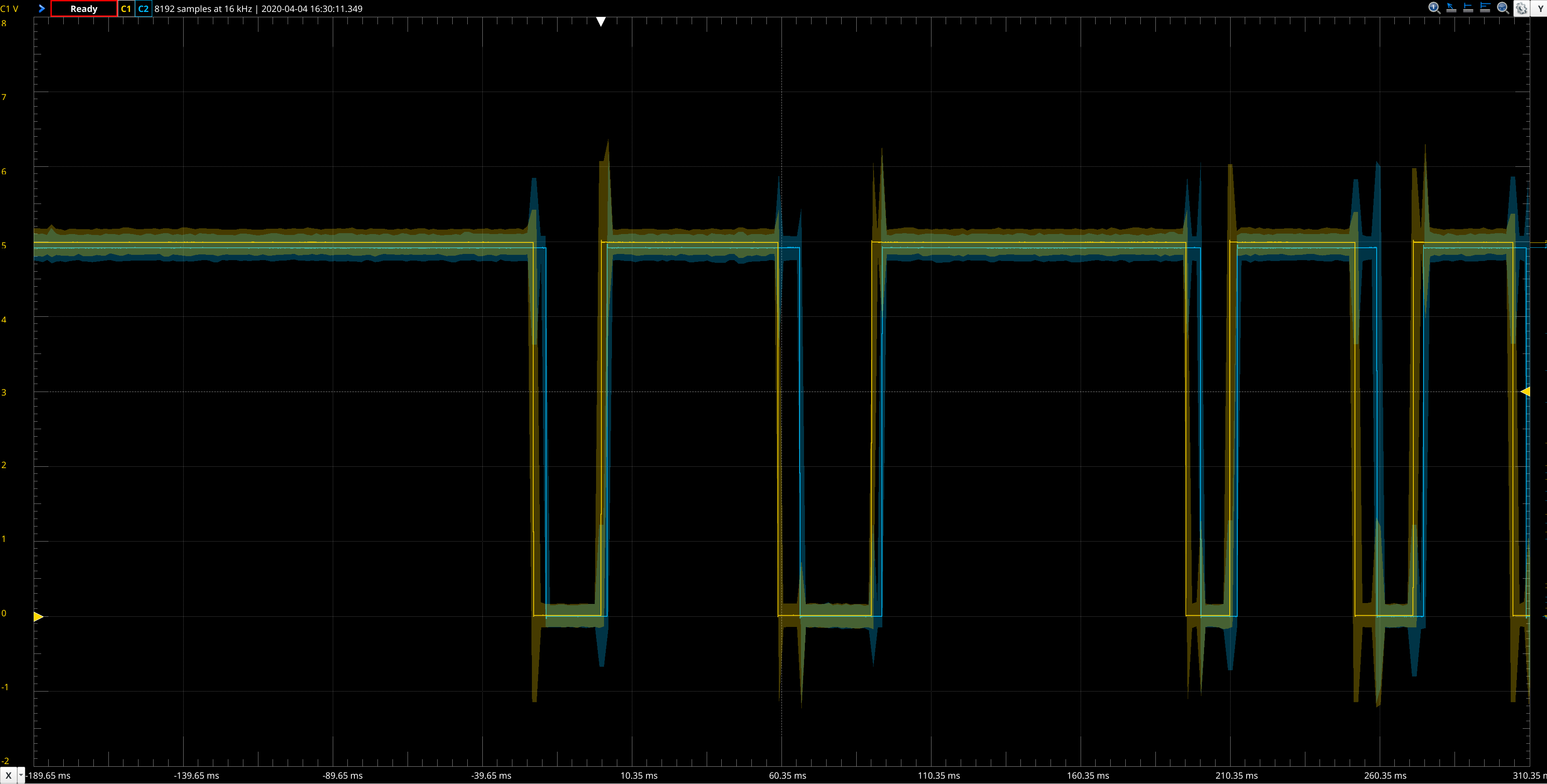
The two plots plots are generated based on the 2 output pins that are toggled when the interrupt is executed and according to the input pins state.
#define __AVR_ATtiny85__

#include <avr/io.h>

void setup()
{
  // PB0 and PB1 outputs
  DDRB |= _BV(DDB0) | _BV(DDB1);

  // PB2 and PB3 inputs
  DDRB &= ~(_BV(DDB2) | _BV(DDB3));

  // set default high
  PORTB |= (_BV(DDB0) | _BV(DDB1));

  cli();                                  // Disable interrupts
  GIMSK |= _BV(PCIE);                     // Enable Pin Change Interrupts
  PCMSK |= _BV(PCINT2) | _BV(PCINT3);     // Turn ON interrupt pins
  sei();                                  // Enable interrupts
}

void loop()
{
}

ISR(PCINT0_vect)
{
  if (bit_is_set(PINB, PINB2)) {
    PORTB |= _BV(PB0);
  } else {
    PORTB &= ~_BV(PB0);
  }
  if (bit_is_set(PINB, PINB3)) {
    PORTB |= _BV(PB1);
  } else {
    PORTB &= ~_BV(PB1);
  }
}
ADC measurements
Using a potentiometer is another possibility to input data into the controller. Based on the read value the PWM can be adjusted in order to control the luminosity of a LED.
#define __AVR_ATtiny85__

#include <avr/io.h>

void setup()
{
  // set the pin as output
  DDRB = _BV(DDB1);

  // set the fast PWM output on OC0B, Inverting Mode
  TCCR0A = (3 << COM0B0) | (3 << WGM00);

  // clkI/O/64 prescaler and Fast PWM to 0xFF from BOTTOM
  TCCR0B = (3 << CS00);

  // comparator value
  OCR0B = 255;

  // VCC used as Voltage Reference, disconnected from PB0 (AREF).
  ADMUX = _BV(ADLAR) |      // left shift result
          0B0010;           // use ADC2 for input (PB4), MUX bit 1

  ADCSRA = _BV(ADEN)  |     // Enable ADC
           _BV(ADPS2) |     // set prescaler to 128, bit 2
           _BV(ADPS1) |     // set prescaler to 128, bit 1
           _BV(ADPS0);      // set prescaler to 128, bit 0
}

void loop()
{
  ADCSRA |= _BV(ADSC);
  loop_until_bit_is_clear(ADCSRA, _BV(ADSC));

  // get the sample value from ADCH and store-it in the comparator
  OCR0B = ADCH;
}
Programing using ICSP
Using the USBTinyISP programmer the uC can be flashed. In this way the bootloader will be overwritten and the full flash can be used.
The bootloader can be afterwards reflashed. It can be downloaded from https://github.com/micronucleus/micronucleus.